|
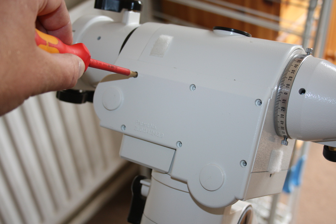
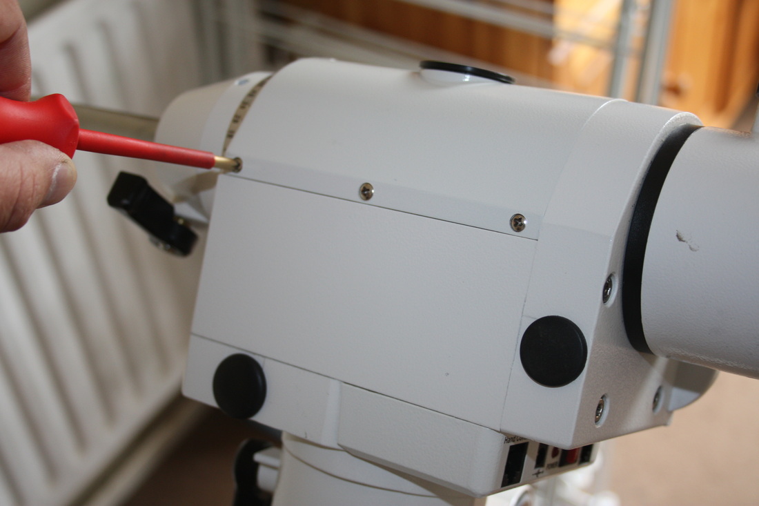
I finally got around to doing the installation of my belt drive kit and thought it would be good to do a blog post documenting the process. I purchased the kit from Rowan Astronomy who are based in Banbury in the UK for the cost of £89.95. I also bought the optional pinion gear extractor for £9.25. I went for the Rowan kit as it maintains the 9:47 ratio that the Synscan handset needs in order to function correctly. A lot of the other kits I have seen use a 4:1 ratio which means that the mount has to be used with EQMOD in order to work correctly. I currently do not own a Synscan controller but like to leave my options open. The kit itself comes with a set of instructions and this blog is in no way meant to replace them. It is simply me following the instructions to see how well they and the upgrade itself work. I should also add that I have no affiliation to Rowan Astronomy. Before we start it's worth watching the first part of a "before and after" video that I have made. It can be found here So lets see what my £99.20 got me 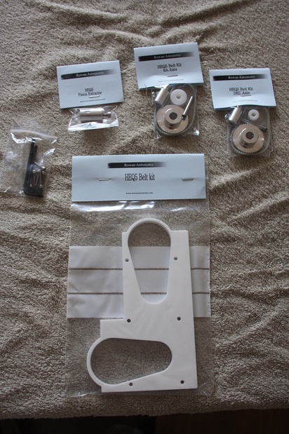 When unpacked it doesnt look like much. You get a set of pulleys and belt for the RA drive and a set for the DEC drive, a set of allen keys, the 8mm spacer, the optional pinion gear extractor and a set of instructions. The supplied instructions are in black and white but you can download and print a colour set from the Rowan Astronomy website here. We do need to take into account that these are precision machined parts and are not mass produced. This is clear in the quality and finish of each item which is very good. Only time will tell if the claimed improvements will weigh out the cost. So what are the claimed improvements? Looking at the Rowan Astronomy website they claim "The pulley modification reduces the spur gear errors that are typical and therefore reduces tracking errors. The belts also make slewing much quieter eliminating the 'grinding' noise that the standard spur gears produce. The pulley ratio is the same as the factory gears. This means the Synscan hand controller is unaffected by this upgrade. All Synscan functions will operate as before." eliminate backlash, smoother tracking and improved PEC are claims I have seen on the internet on various forums which can fall under "tracking errors" but no direct refference to specific error improvements on the Rowan Astronomy website which is fair enough. So now its time to start taking the mount apart. I have to admit that I have been a little apprehensive about doing it. Part of me was in the "If its not broke dont try to fix it" camp but the part of me that enjoys tinkering won out in the end and I had to do something about that awful grinding that the motors make when starting and stopping, at 2am in the garden it just seems so loud!! To start with it is a simple case of removing the gear and DEC shaft covers. 6 screws in one and 5 in the other
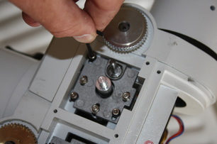
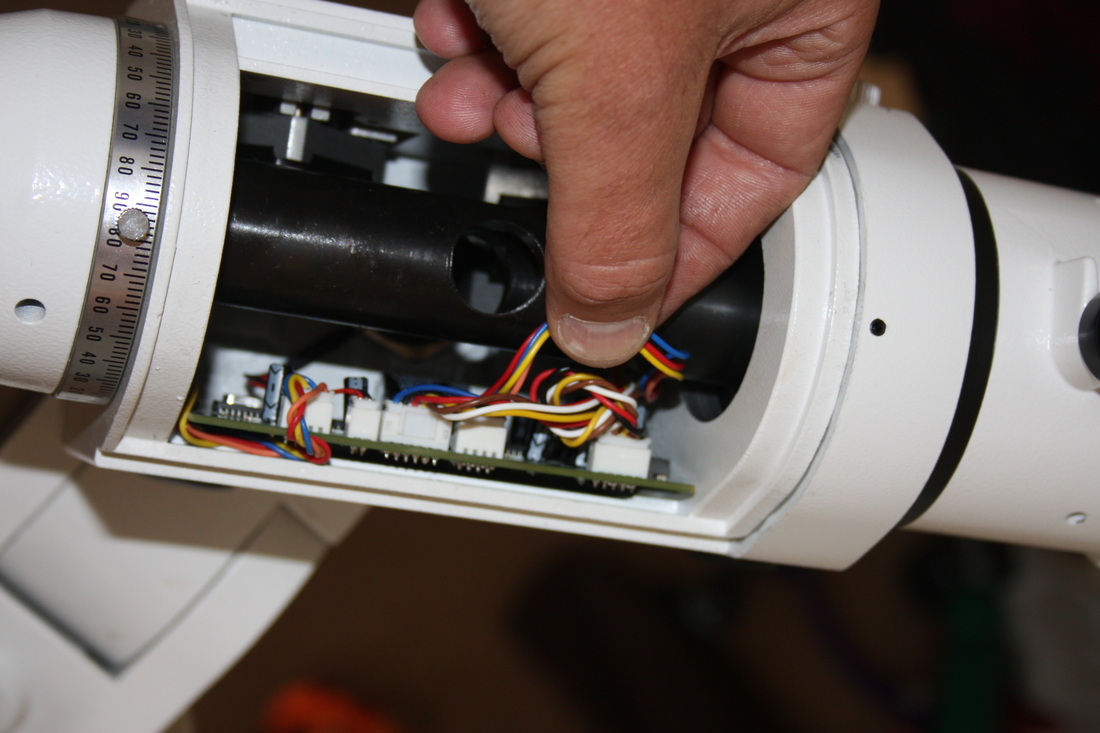
This leaves the gears and control board exposed. If you want to do a before and after sound check on the drives now is the time! 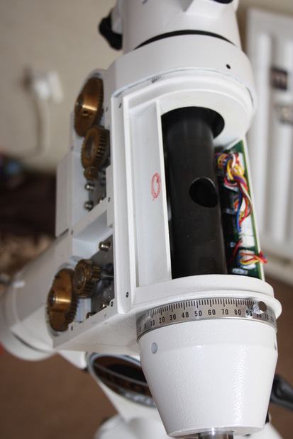 Next we need to identify which cable is the RA motor and which is the DEC motor. The instructions have arrows that point to the respective plugs on the board which helps a lot but they are not to hard to trace. The only thing I found was that the cables were all twisted together in a knot to keep them clear of the DEC shaft. Not a big issue but care must be taken to unwind the cables from each other (a bit fiddly) and unplug the DEC motor cable from the board. Its a good idea I think to follow the advice on the instructions and work on one drive at a time 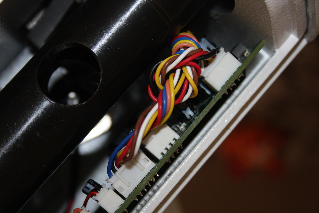 Next stage is to undo the 3 bolts holding the motor and plate in the mount again the bolts are marked on the instructions but it is fairly obvious. Carefully remove the motor keeping an eye on the wires and threading them through the housing 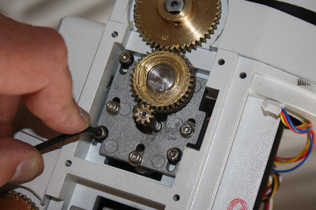 The larger gear and pinion slides out easily once the 2 grub screws are undone. This is no longer needed so can be disposed of if you wish or keep it as I dont see any reason why this mod can not be reveresed. 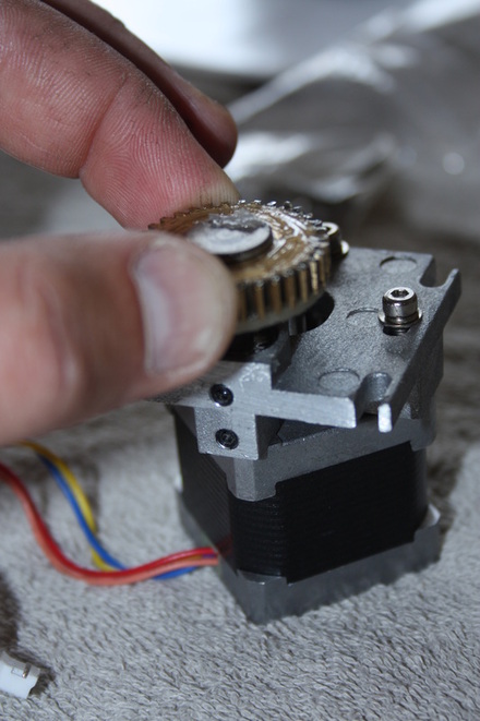 Once the larger gear and pinion is out the plate that sits on the motor needs to come off. This incolves removing the last 3 bolts. Be sure to keep these seperate from the first 3 as they are different lengths. It also mentions in the instructions that, to save time when re-building you need to note where the wires come out of the motor in relation to the orientation of the plate. When you get to this stage it becomes apparent that this is a good idea! I marked the plate and motor in one corner as seen in the picture. 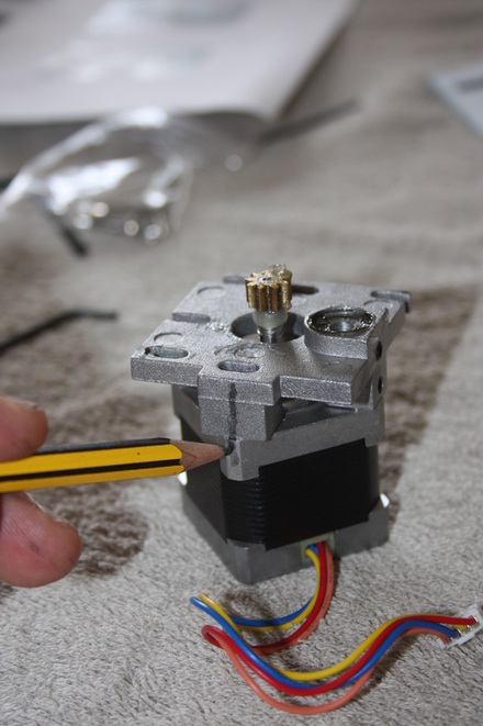 With the plate removed the smaller gear can now be accesed using the optional pinion gear extractor. For the sake of £9.25 I would strongly reccomend this unless you already have something that will do a similar job. Just trying to pull the gear off the shaft with pliers would be difficult and may bend the shaft which obviously would be disasterous. You will need to employ a pair of pipe grips or something to hold the extractor while you turn the allen key. 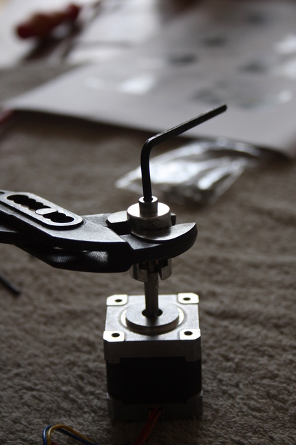 Just to add a note to the above. The screw in the gear extractor wasnt actually long enough to pull the gear fully off of the shaft. With the screw wound fully in the shaft was still around 2mm inside the gear. This meant that I had to very gently lever the gear off using pipe grips under the gear pulling upwards which was a shame (and goes against what I said above). I dont think this is a fault with the extractor itself as it worked perfectly on the RA motor. Possibly a slight difference in gears, who knows? With the gear removed the new 9 tooth pulley can be slid onto the shaft. The instuctions mention leaving a 5mm gap between the motor and pulley but to be honest I found that the pulley slid down as far is it could go and this naturally left the correct spacing. 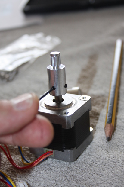 The shaft that will hold the idler wheel is place into the motor plate and should finish flush with the top of the pulley as in the picture. I found the shaft to be a tight fit and it needed a little tapping from a rubber mallet to get it down. Once in place the 2 grub screws are re-tightened. 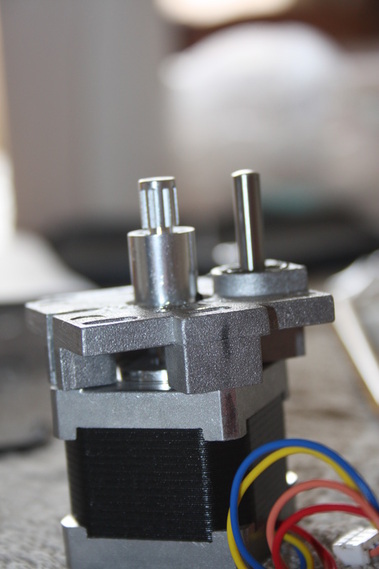 The motor plate is then fixed back to the motor 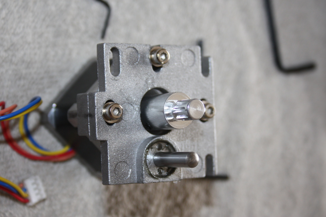 Now we need to turn our attention back to the mount. The large cog that is attached to the worm gear needs to come out. Make sure you undo both grub screws. I didnt read the instructions properly and was trying to prise it off with a screw still tightend. The instructions mention that it may need a little levering to get it off but once both grub screws were undone it slid off easily. 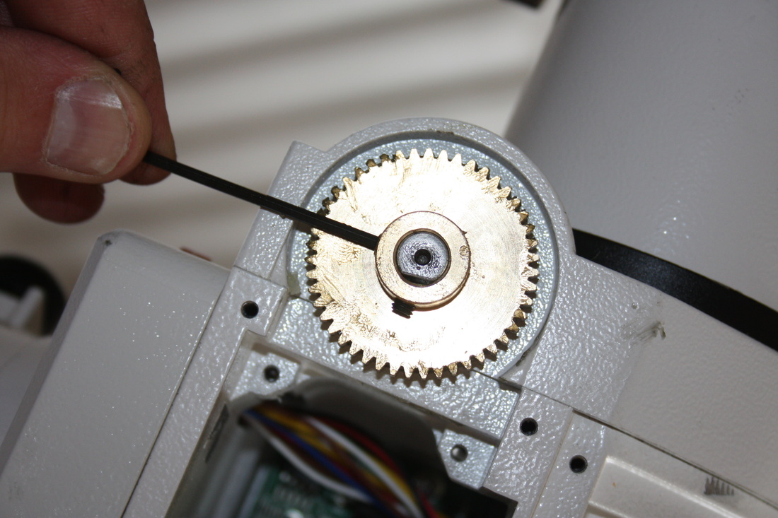 Once off you can then fit the new pulley in its place. I tried to line up one of the grub screws with the flat spot on the shaft but I think the screws are too low down to catch it. I dont think this will be an issue as 2 screws should hold it nicley. 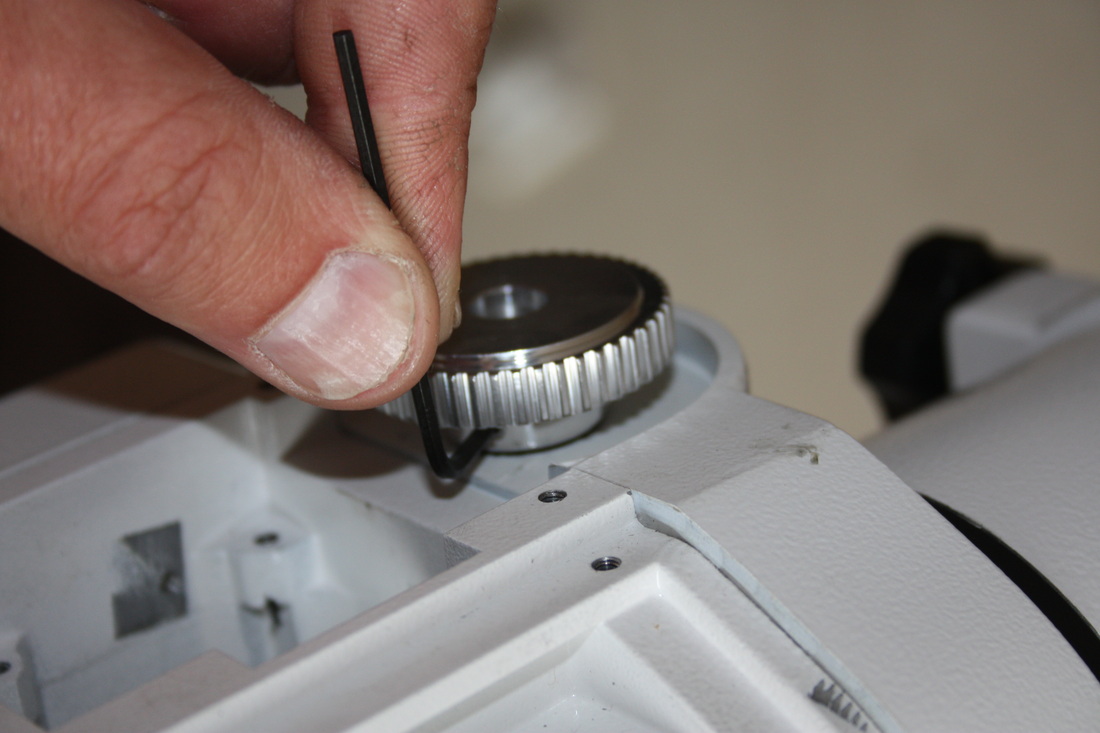 At this stage you could turn the pulley by hand to make sure it is rotating the worm gear. Once satisfied the motor can be reintroduced into the mount housing leaving the fixing screws a little loose and feed the wiring carefully back up to the control board and plug it back in making sure the wires are clear of the DEC shaft
then slide the idler over the pin which is not fixed and is allowed to move freely and feed the belt over the pulleys and idler as shown 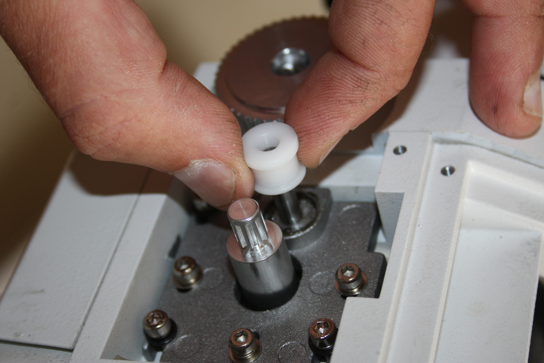 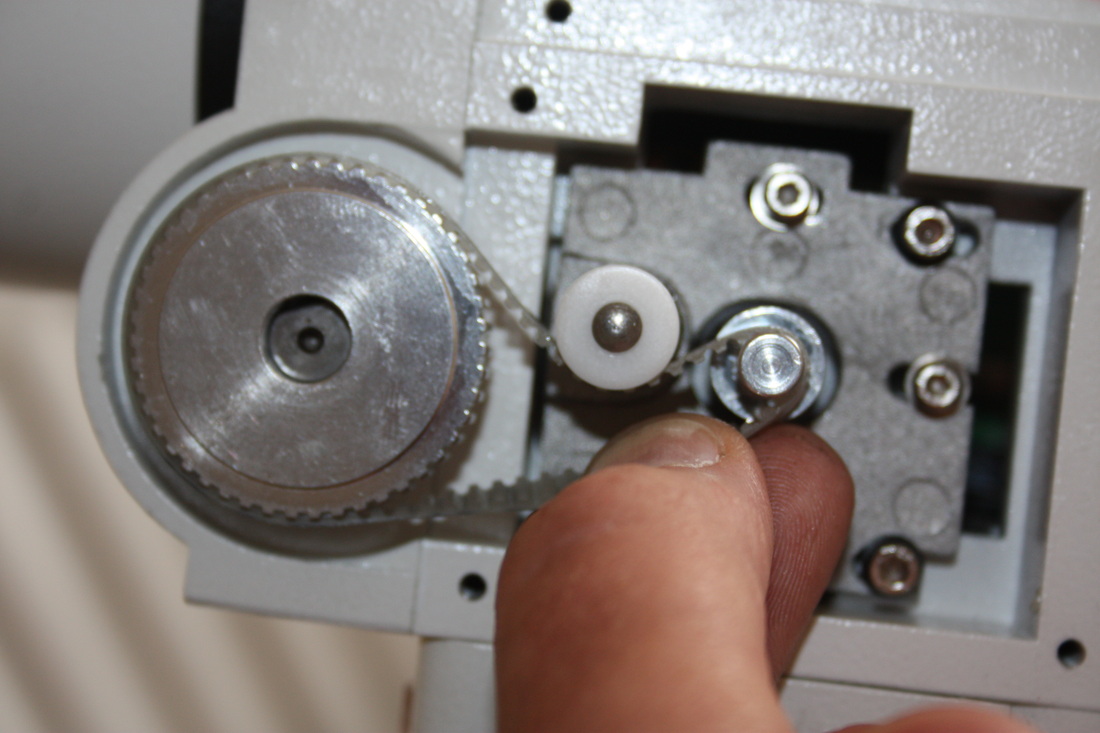 The motor can then be slid back away from the worm gear pulley to tension the belt as described in the instructions and the 3 screws tightened to hold it in place. Now is a good time to test the DEC drive to see how it performs. When if fired up the mount every thing was running very smoothly with no slipping. I should add that this was done with no load on the mount that will be tested at a later date. The only slight issue I noticed was that the belt moved up and down on the pullyes a little depending on which way you ran the mount. This first picture shows the belts position aftering running the mount in one direction. The belt showed no signs of moving any further than this. 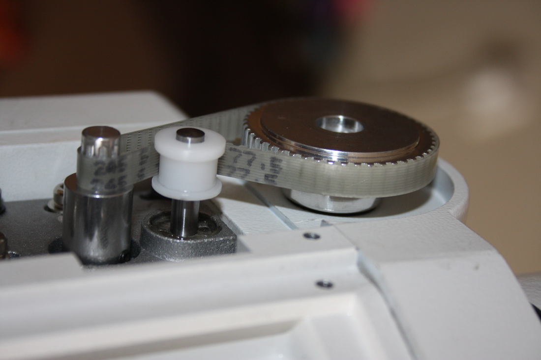 This second picture shows the belt position after running the drive in the opposite direction for a while. As you can see it has moved up the pulley a fraction. Again it got to this position and stopped so I dont think there is any risk of it coming off. This must be something to do with the alignment of the 2 pulleys but to be honest I cant see that it will be a big issue but we shall see when it comes to testing the mount properly 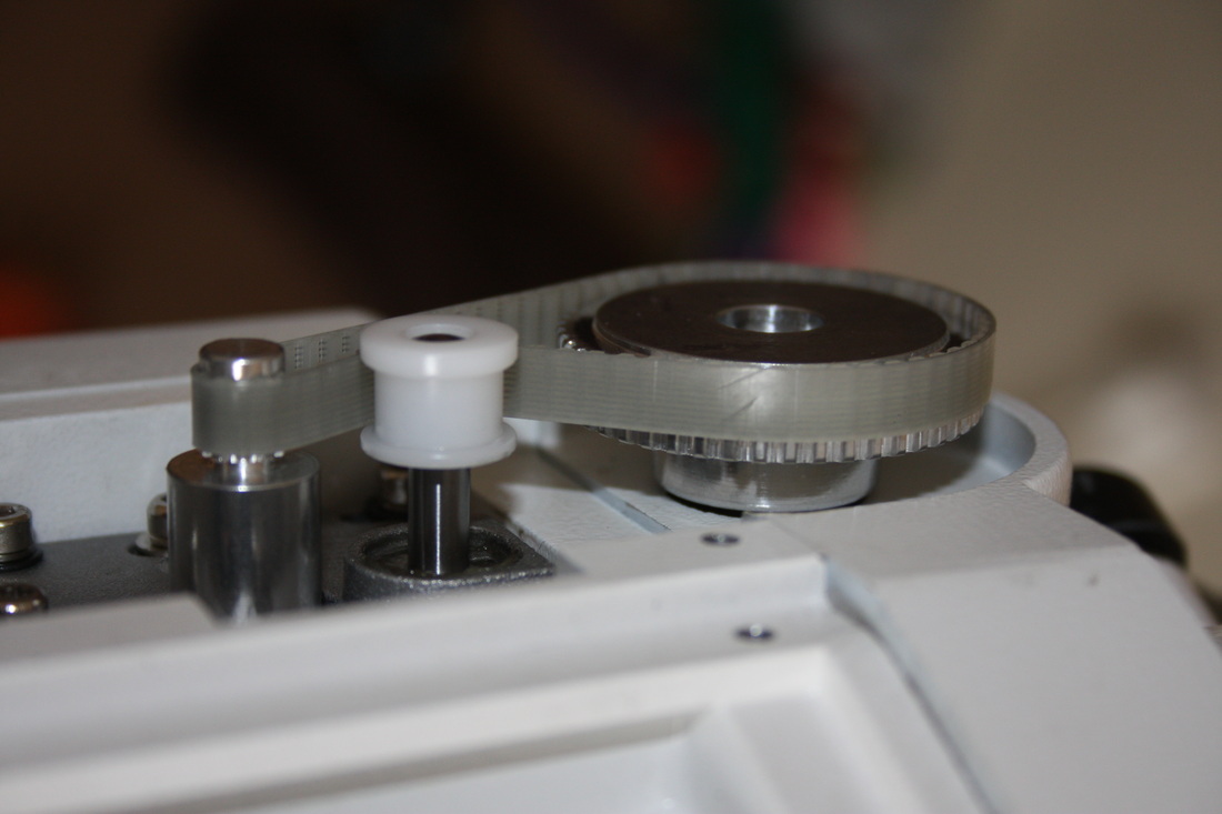 The install process is the same for the RA axis so just go back over the instructions. You will probably find now that you have done one drive that the RA conversion will take you less time to complete. When finished it should look like this 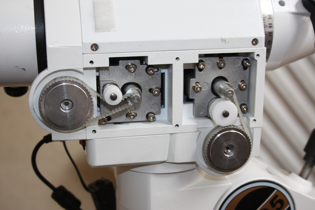 Now head back to the Youtube video to watch the "after" part to see what they sound like Then it is simply a case of fitting the covers back on including the new 8mm spacer and checking everything works. Straight away when I got to this stage I could here something rubbing on cover when turning either axis. It is difficult to tell exactly what it was but having taken the cover back off I could see that one of the small pulleys had left a grease mark on the cover which was a big clue. I contacted Rowan Astronomy and asked for advice from the online community and found out that this is not an isolated problem. It is due to a 1 or 2mm difference in the casting of the mount housing which raises the whole motor assembly up just a fraction. Rowan Astronomy were exellent in their response and sent out some small 2mm spacers that will sit between the motor and the motor plate to sink the pulley in just a small amount (2mm). I have not fitted them yet but just to give you an idea I have illustrated the picture below 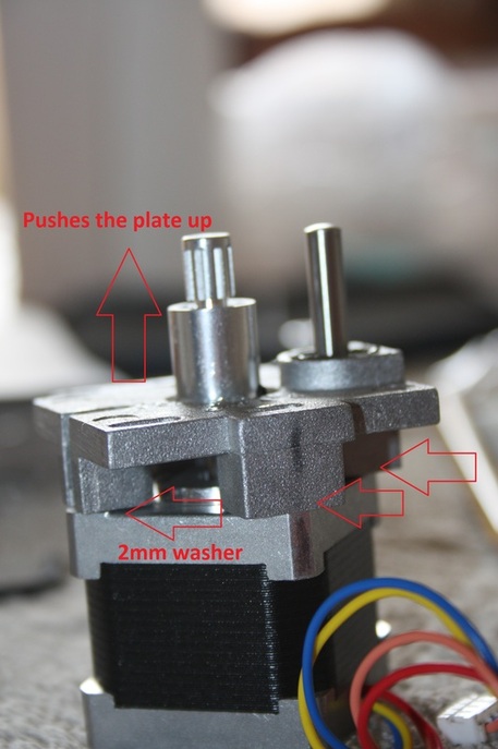 I am very happy with the install part of this upgrade. So far, so good the noise that the system used to make when starting and stopping has gone. The service from Rowan Astronomy has been excellent and its safe to say the supplied instructions make this a fairly easy mod providing you have a little DIY skill. I think the only real issue is the very slight differences in the mount housing dimensions but its impossible to cover all posibilities out of the box.
I would like to go right ahead and reccomend this to anyone who is thinking of doing a belt upgrade to their HEQ5 but ill will hold fire until I have tried the mounts tracking and guiding and checked im happy with what im getting Im looking forward to testing the mount to see how it performs. I shall report back my results!
3 Comments
Ed Mizzi
27/4/2016 12:58:19 pm
Hello Steve, I just completed my installation of this kit and thanks to your description and photos, it went well. Of course, the proof will be in the pudding once I have tested it by imaging. I am glad you mentioned those 2 mm spaces as otherwise I would not have known to ask Rowan to send them to me. I must say that it was frustrating getting the belt to stop riding up a little in one direction. I had to uninstall and re-install the RA parts 3 times to get the idler wheel, idler, etc. lined up as perfectly as possible. And I agree, the service from Rowan was second to none. Thanks from Waterdown, Canada...Clear Skies, Ed
Steve Bassett
29/4/2016 03:49:13 pm
Hi Ed
steve bosley
5/3/2018 04:15:37 pm
Very clear and exactly as I recently did (apart from the 2mm washers) but with one significant exception. The 32mm pin came with a (5mm?) well engineered spacer with grub screws to secure, and a screw that sank into one end of the pin (to secure the pulley ?). Well I installed exactly as per the instructions and so have the spacer and screw left over for each drive. All seems well, but I'm concerned about the leftovers. Leave a Reply. |
Steve BassettLiving on the South coast of England. Amateur astronomer Archives
July 2014
Categories
All
|
| Sompting Astronomy |
|
 RSS Feed
