|
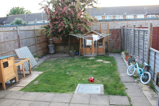
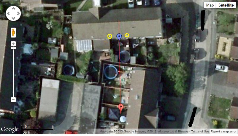
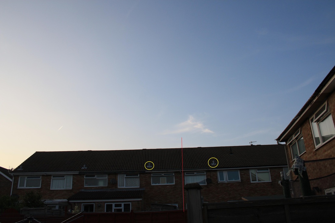
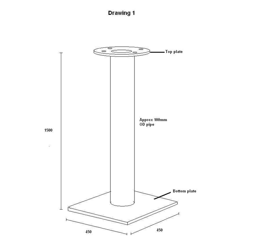
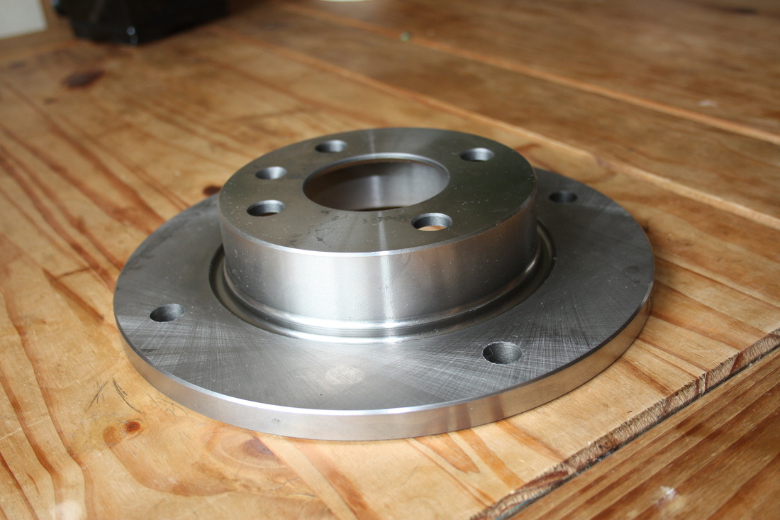
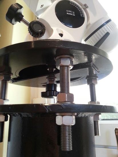
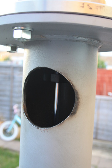
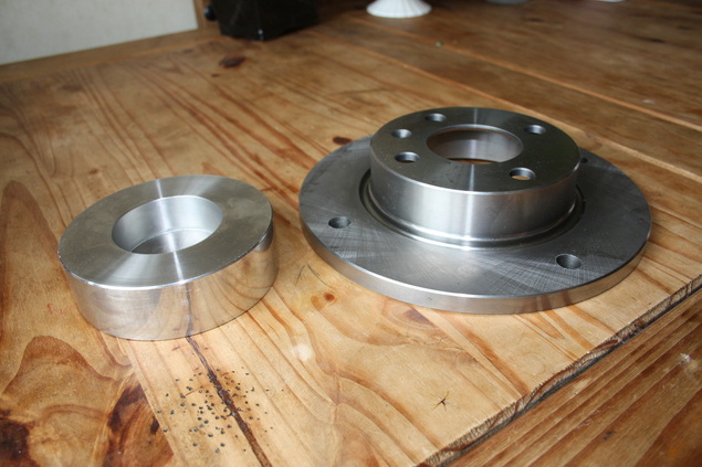
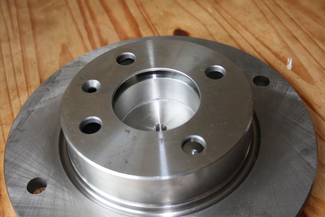
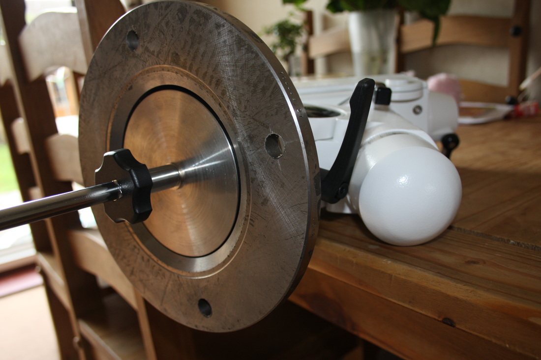
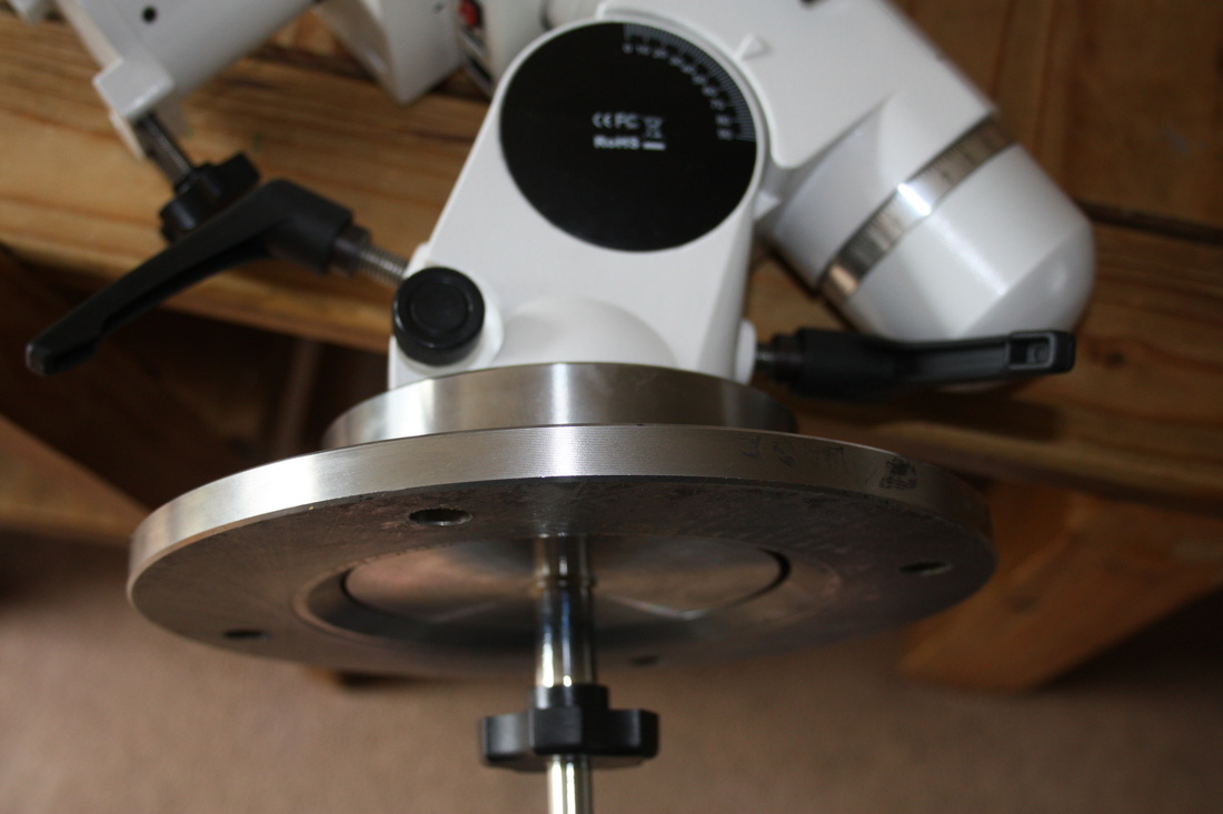
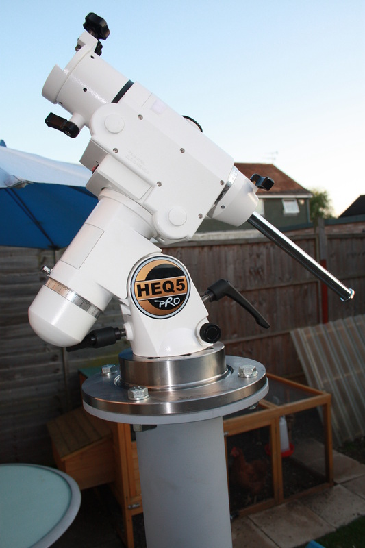
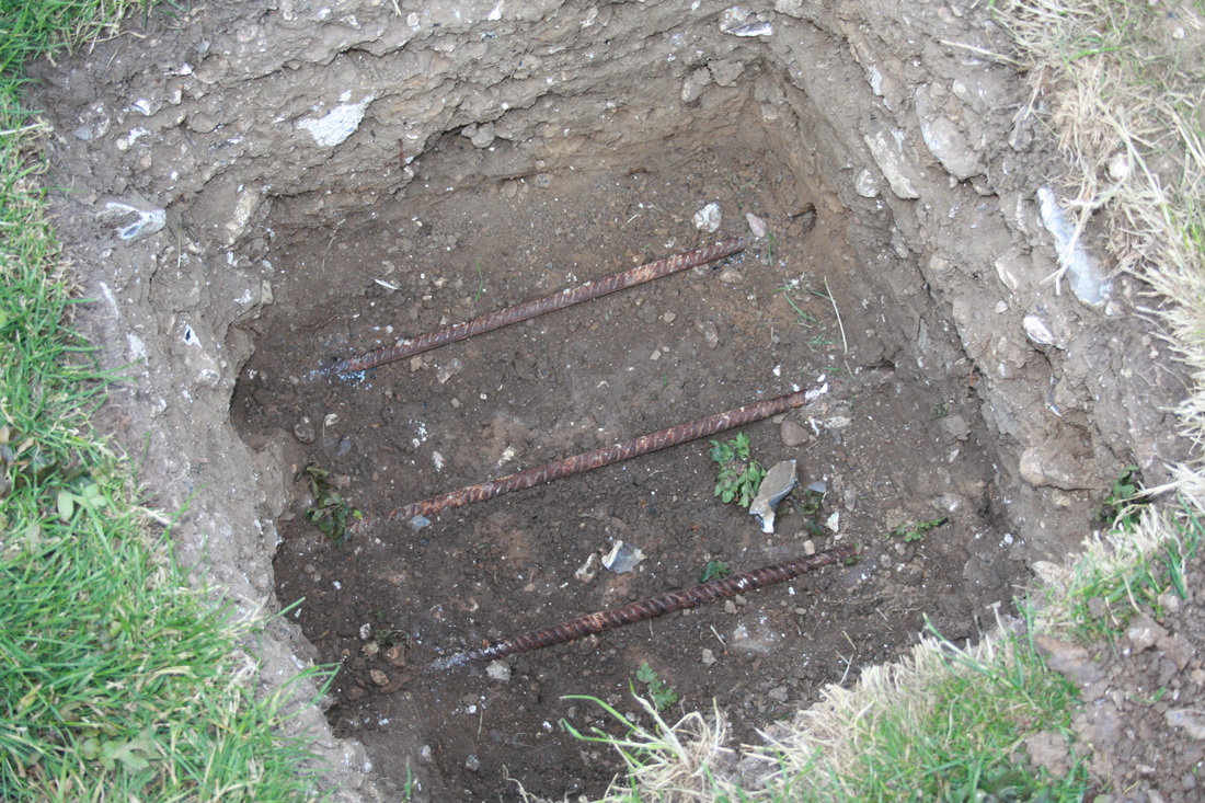
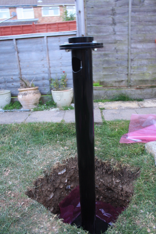
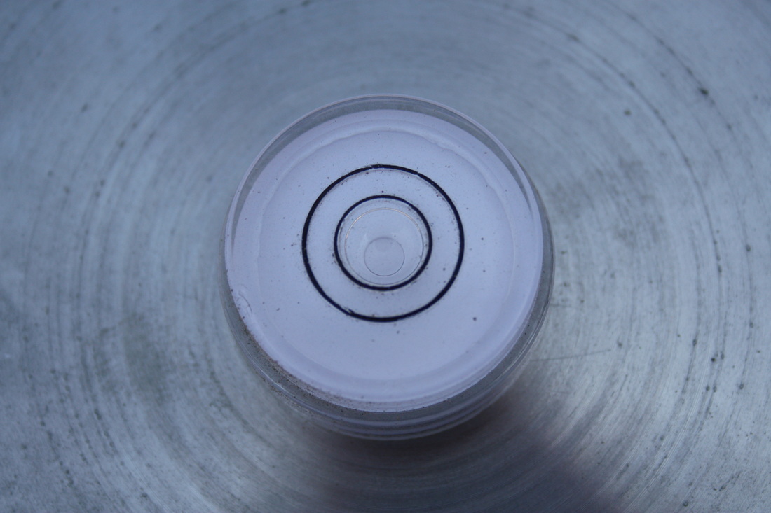
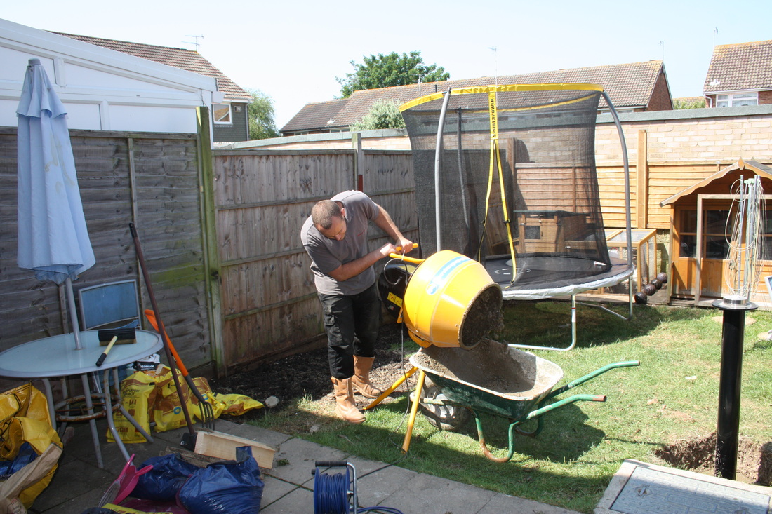
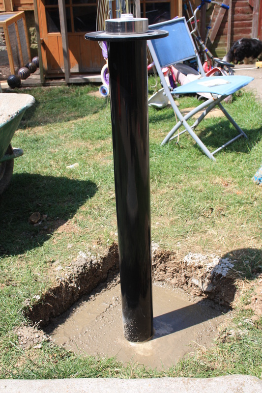
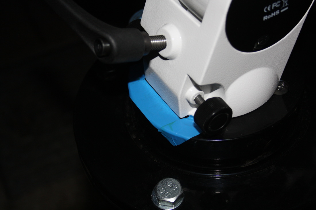
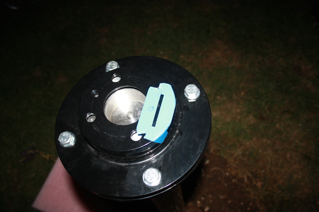
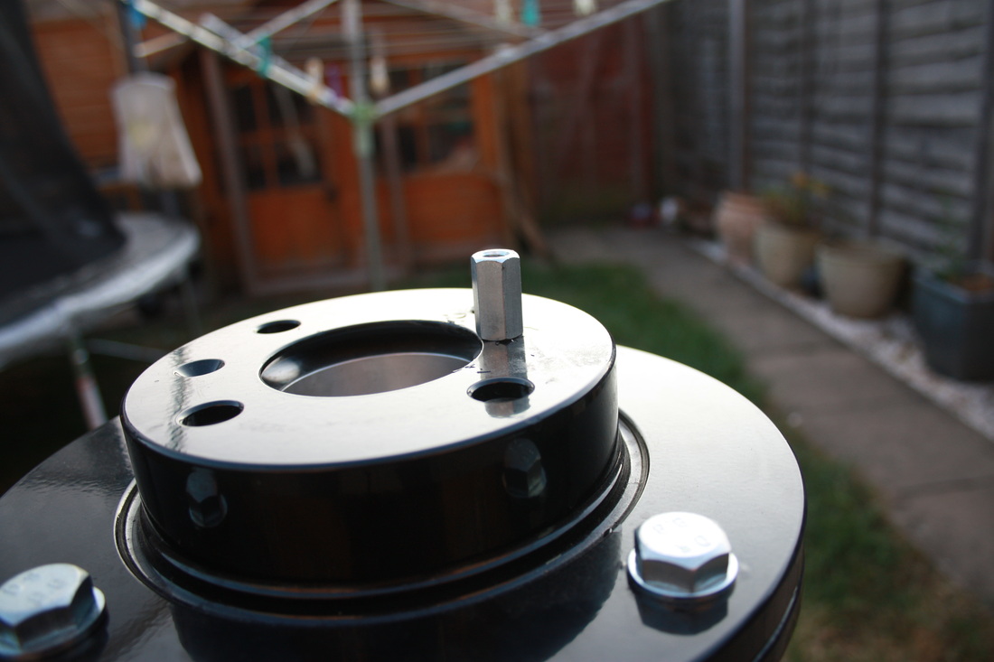
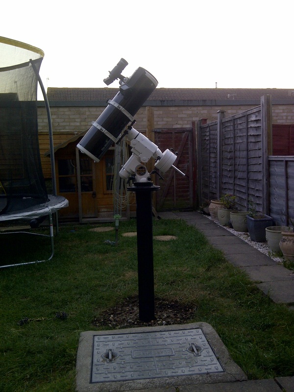
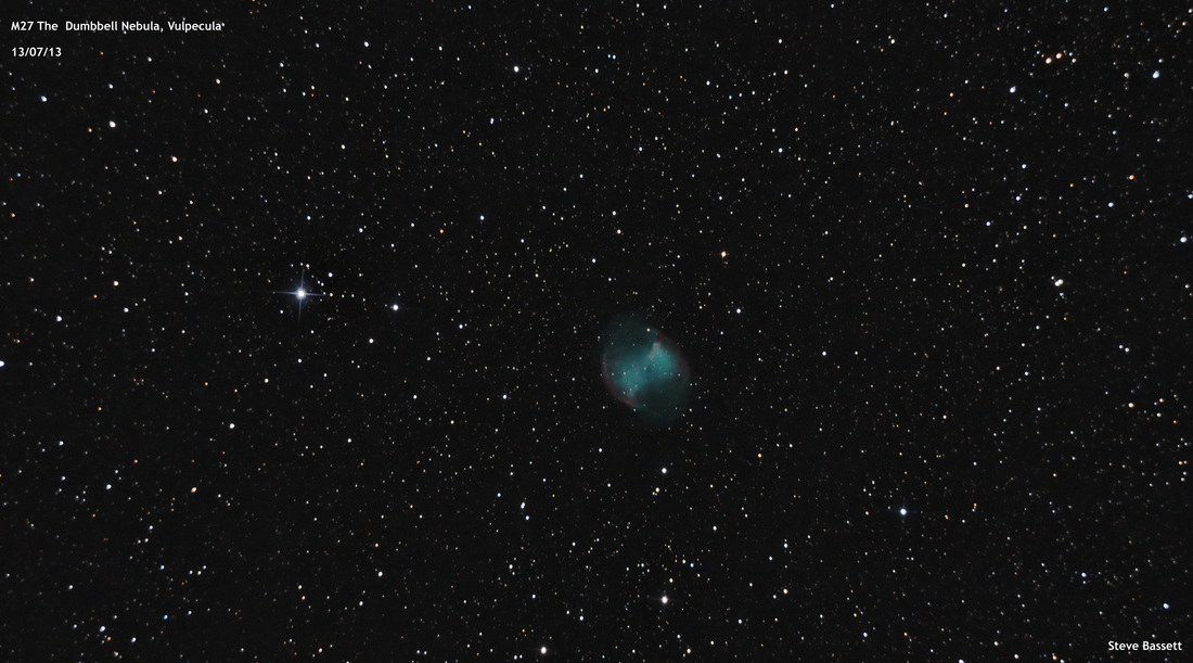
1. Location I decided about a year ago that I wanted to try and improve my astro imaging so as well as an upgrade to an HEQ5 pro I also wanted to try my hand at building and installing my own pier in the garden. I started by doing my homework, numerous hours trawling the net for ideas, methods, do’s and don’ts. The pier had to be aesthetically pleasing as well as solid and functional. After I had an idea of what I’d like to end up with the next task was location. So here is my garden. It’s small and doesn’t have a great deal of space to play with. I needed to place the pier in a position that would give the best possible views whilst also not impeding on the garden too much. I decided to go for an area roughly in the same place as the red ball (yes I did put it there for the purpose of the picture). The garden provides views North, South and West (East being blocked by the house) down to around 20/30 degrees above the horizon. It is important to ensure you know the direction of true North. The more accurately you set your pier to this the easier your polar alignment will be. This Website is very good for determining true North. You simply find the location of where your pier is going to be sited and put down the marker. This gives you the longitude and latitude co-ordinates. You then add another marker keeping the same longitude but increasing the latitude a little towards the North. This gives a 2nd point that is exactly (true) North of you pier location. Unfortunately when the picture was taken we had a gazebo in the garden so I had to estimate the rough location indicated by the red marker. The blue marker is true north which puts it roughly between the 2 vent stacks on the roof circled in yellow. 2. The Pier Now the location and a rough direction were set it was time to look at the pier itself. I wanted to have around 900mm to 1 meter above ground and decided on around 500mm to 600mm below ground with a square plate on the bottom encased in concrete. A quick design in MS paint and I ended up with this. I was lucky enough to acquire some left over pipe and some 13mm plating from work which along with these drawings were given to the fabricator to be cut and welded for which they charged me £30. I needed now to come up with a way of attaching the mount to the pier and found a few examples on the web that were using car brake discs. One of the sites listed the disc I would need to take my HEQ5 perfectly. I found it on eBay for £10, turns out it was for a Skoda Favorit The dimensions are Overall diameter = 236mm (this governed the diameter of the top plate I had welded to the top of the post) Overall height = 46mm Centre hole diameter = 62mm Disc thickness = 12mm A commonly seen method for attaching disc to the top plate of the pier is to raise the disc a few inches above the top plate using threaded rod. This then allows you to access the underside to tighten and undo the hold down bolt of your mount and also allow levelling adjustments as shown in the image below Purely from an aesthetical point of view I wanted to try and avoid this although I don’t think it makes any difference in stability. To achieve it I had to overcome 2 main issues. Firstly how was I going to gain access to the hold down bolt if it was down inside the pipe? And secondly without the threaded rod how was I going to level the top plate? To access the hold down bolt I insured I had a 100mm hole in the top plate and I simply cut a 70mm hole in the side of the pipe. This allows just enough room to get a hand onto the hold down bolt to tighten and undo. I had a large stainless steel “washer” made up that fitted nicely inside the boss of the brake disc with an M10 threaded hole in the centre. The recess in the washer was cut deep enough to allow the mount to sit flush with the top of the disc and allow for the thread of the hold down bolt to protrude through without touching the bottom of the mount. It was important to ensure that the washer was larger than the 100mm hole in the top plate to stop it dropping to the bottom of the pipe when the mount was not attached. The hold down bolt is then screwed through the threaded hole in the washer and the whole assembly inserted into the disc. The mount is then added to the top of the disc and the hold down bolt is wound into the mount thread until tight. This holds the whole thing together nicely. I then bolted the whole thing to the top plate to test it and was very happy with the results. I was satisfied that it was time to put it in ground!! 3. Time to dig a hole! It was a few weeks after my first initial tests that I got a chance to start work on the hole. In that time I also had the pier and disc powder coated in gloss black, I knew where the hole was going (see first picture) and I knew that I was aiming for around a 500x500x600 deep hole. This would be the first time id had a go at something on this scale but I had an assortment of tools to assist including a 100mm manual post auger, a pick axe, a pair of scissor shovels and the customary garden spade and fork. I know very little about ground work but I do know one thing…….flint is hard!! And when you are digging a hole in ground that seems to be more flint than earth it is pretty hard going! As it turns out the combination of pick axe and garden spade seemed to work best until I got down deep and had to use a trowel to excavate what the pick axe had loosened. It took the best part of day to dig the hole but was kind of satisfying (not to mention a relief) to see it finished The second issue about levelling now needed to be addressed however, having a perfectly level pier is not essential and polar alignment can still be achieved so I was going to be happy as long as I could get close to level. I added some reinforcing bar to the bottom of the hole and levelled them as best as I could. Nothing technical just a hammer and a spirit level checking in all directions. Once I had them somewhere close I mixed up a small bag of post-Crete and poured this into the bottom making sure it covered the bottom and buried the re-bar. I allowed this to harden a little before trowelling it over again getting it as close to level as possible I also added some polythene sheeting which I hoped would help with moisture. It was now time to carefully lower the pier in and allow it to sit on the re-bar. This forced the still workable post-Crete around the side of the bottom plate and formed a nice barrier (as far as I could tell) between the ground and the plate. Possibly all a bit OTT but I thought better that way as it was a simple thing to do I put a small circular spirit level on top of the pier and manipulated the whole thing until I was happy it was level and managed to get it very close. Over time I expect the pier will go out of level as the ground moves but I’ll keep an eye on it worse case is that I’ll have to raise the disc up using threaded rod or perhaps add some shims but only time will tell. I then had to mix and add the concrete. In the end I used 16 bags of B&Q’s ready mix concrete which was more than I had imagined needing and was very grateful for the loan of cement mixer. We were fortunate enough to get some prolonged good weather so I picked a day and went for it with assistance from my wife. You may also notice that the tree at the back of the garden has gone!! It was simply a case of pouring the concrete into the hole whilst all the time checking the spirit level on top to make sure there was no movement. I finished the concrete around 100mm from the top of the hole to allow me to add top soil and grass seed when the concrete had cured and left it for around 1 week to harden checking the level every now and then to see if it had moved. The next task was to add a small spigot to the top of the disc for the azimuth adjustment screws of the mount to work against. Although I had made my map showing me where true north was I decided it was far easier to attach the mount and perform a polar alignment of it to give me my true north position. I cantered Polaris in the polar scope using the altitude bolts but manually twisting the mount in azimuth. My thinking was that if Polaris was centred in the scope cross hairs and I took that as my true north direction I would have enough azimuth adjustment in both directions to properly polar align. Once centred, I marked the mount outline with electrical tape. This left me with an idea of where to drill the hole when the mount was removed. I measured the thickness of the metal and added another strip of tape. The pencil mark shows where I needed to drill I drilled an 8mm hole through the disc and attached an M8 threaded rod connector which is just high enough for the azimuth bolts to hit. Tests using the azimuth screws showed that it works perfectly and here is the finished pier with mount and scope attached. Going forward I plan to add something to the top when the mount is not attached possibly a sun dial or a bird table just to give the post another use. I may also fill the post with cement or maybe just sand as it is possible to drop things down inside the post and it may also fill with water. I have also added my first image taken using this pier. For the first time I took 180sec exposures which is pretty good for an unguided set up but I plan on trying 240sec next time. In conclusion I really enjoyed doing this project and if anyone is considering having a go I would say go for it. The stability that I get now for both observing and imaging has improved considerably my only wish is that I could take it out into the field with me and use it under truly dark skies. I
hope this write up has provided some inspiration and ideas to help get you started. If anyone has questions or would like advice I can be contacted via email at [email protected]
3 Comments
|
Steve BassettLiving on the South coast of England. Amateur astronomer Archives
July 2014
Categories
All
|
| Sompting Astronomy |
|
 RSS Feed
